top of page
Underwater dipole antenna

Underwater RF data communication

A project in progress.
Based on the AX5043 radio transceiver.
For use in fresh water (conductivity 500...1000uS/cm).

Wireless bi-directional RF data communication system for real-time remote control of a submersible vehicle.

​

The system described here can be categorized as RF test equipment. It has not been tested for compliance with regulations regarding the transmission of radio signals. It is the responsibility of the user to use this equipment legally.

turtle_1777 - kopie_edited.jpg

About

Exploring new applications.

Radio communication underwater is a challenge. In my spare time, I am working on a long-term project related to experimenting with different control strategies for depth stabilization of a model submarine. Making changes to the software in the model submarine is a cumbersome process because the model must be taken out of the water and partly dismanteld. The system proposed here is intended to solve these problems by moving the computer from the vessel to the shore.

​

More detailed information is available on request.

Submarine

Objective

Evaluate underwater sailing behaviour.

Wireless control of a submersible vehicle, like for instance a model submarine, in a such way that it is easy to modify software, parameters or algorithms on the fly and at the same time being able to observe the effect of these measures on the course and stability of the vessel.


Desired characteristics: in compliance with radio regulations, friendly to marine life, flexible with respect to the used communication protocol, small dimensions and low cost.


image Saab AB

Model submarine used for analysis purposes

How and why?

In the image above, the submerged vessel is fixed with the purpose of measuring, for example, the water drag of the hull. Inside the vessel there are no means available that support manoeuvring.

By omitting the mechanical guiding rods and placing mainly sensors and actuators inside the vessel, the model can be controlled with a program running on a remote computer. Because the computer is located elsewhere, real-time and bi-directional data communication between the underwater vehicle and the computer is needed. This is the main function of the system presented here.

The effects that changes to the computer program have on the course and stability of the vessel can be visually observed instantaneously. With respect to the image above, a research question could be, for example, how well the underwater vehicle is able to maintain its position as a function of the velocity of the water flow.

Underwater communication with cables

Wherefore/for whom?

  • Fewer cables in the image above.

  • Model submarine hobbyists.

  • Maritime research centres (hydrodynamics).

  • Research institutes for underwater radio communication.

  • Educational tool technical colleges/universities.

  • Extended/next level evaluation kit RF transceiver.

  • Those interested in real-time underwater remote control.

  • AUV wireless data download.

  • Exchange of data between underwater devices.

  • Mutual communication in swarms of underwater devices.

  • Applications not yet foreseen.

  • And last but not least, for fun!

Test platform

Tests

With two prototype PCBs a distance of 6 metres could be bridged (27MHz, 100mW, half-duplex, 590uS/cm). During these tests both antennas where vertical submersed at a depth of 150cm. Because of all the testing the prototype PCB’s have worn and new PCB’s needs to be made. The new PCBs also contain some modifications that are the result of experience gained during testing. .

Communication types

Findings

In the Netherlands the frequency bands 27, 35 and 40MHz can be used for remote control purposes. Unfortunate radio regulations prohibit the use of these frequency bands for the system described here. It is this aspect that forces all radio communication to take place under water (no radio regulations).

​

The lower the frequency, the larger the antenna and the greater the range underwater. Within this respect 13.56MHz offers a good trade-off between range and antenna size.

Available radio transceivers ICs go as low as 27MHz, which results in to less range. One way of overcoming this is to place the antenna ashore in the air. This is however not allowed by radio regulations. Operating the system at 13.56MHz is another way of overcoming the underwater range limitation. For 13.56MHz, for example, homebrew or SDR (Software Defined Radio) could be considered.

​

Summarized, the lack of transceivers for the frequency range of interest (3-30 MHz) and complying with radio regulations do not make it easy to develop  applications such as described here.

Equipment

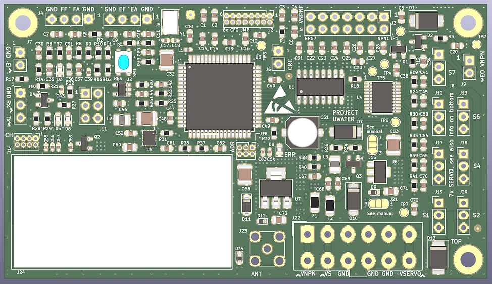
To establish a half-duplex underwater radio link, two PCB's are needed, each with their own antenna.

​

The operating frequency is the 27MHz band (5-Ch.). The protocol is flexible in terms of the amount of payload and data rate.

Research PCB

Research PCB

For measurement and control applications.

Freely programmable or equipped with application-specific software.

Supports a width variety of supply voltages and interface options, including a sensitive 3D accelerometer.

​

Derivative functions such as an RF front-end and a modem are also among the possibilities.

​

95x115mm

​

ITU

In compliance with radio regulations?

It looks like there are no regulations for the transmission and reception of underwater radio waves. As a result, it is difficult to assess whether the use of this equipment is permitted or not.

​

The best strategy seems to be to ensure that radio waves that have their origin underwater do not cross the water to air boundary.

​

Submerge the antennas as deep as possible in the water, use as little as possible transmit power and have a as high as possible receiver sensitivity are methods used to minimize the risk for radio waves to cross the water to air boundary.

​

A portable short-wave radio receiver can be used to check that radio waves do not cross the water to air boundary.

​

RF transformer

RF technology

The RF transceiver is an advanced, high performance device. A lot of attention went into verifying correct operation and optimizing internal parameters. With selectivity and sensitivity in mind the RF front-end is optimized for the difficult radio conditions underwater. The same goes for the antennas.

A pleasant side effect is that underwater antennas can be about a factor 9 shorter than in air. This is due to the lower propagation speed of radio waves in water. A disadvantage is that the electrical conductivity of water affects the resonance frequency of an antenna.​

The image of the RF transformer illustrates that handicraft is not lacking either. Unfortunately, the handwork also indicates the lack of components suitable for lower frequencies. Another example of this is the lack of transceiver ICs suitable for the frequency range of 3-30MHz.

Media comparison

Inland ports and swimming pools are places where people often sail with model submarines. In many occasions these places have a shoring and a bottom made of a hard material with a smooth surface structure, such as steel or concrete. Approximately the same goes for basins of maritime research institutes also. These smooth and hard materials increase the chance for multi-path fading. Within this respect the attenuation of radio waves in water can also be explained as an advantage.

The use of a cable (copper or fiber optic) has not been considered because of the need to be able to sail freely and because a cable could become entangled in the propeller.

Media comparison

FAQ

Programming the PCB?

The PCB is equipped with an ATMEL XMEGA AVR microcontroller. Software tools like CodeVision, BASCOM, Atmel Studio and Arduino can be used for programming.

Future?

  • Inventory of wishes

  • Testing new PCBs

  • Develop antenna for underwater vessel

  • Research to increase the range

  • Search for new/other application areas.

Interface options research PCB?

  • PDI and JTAG programming port

  • Two on-board LED’s, reset button, 8x DIP switch

  • Sensitive 3D accelerometer, USART (3.3V), expansion port

  • Two quadrature encoder inputs

  • Analogue- and digital inputs (each 8x)

  • NPN transistor and 5V logic outputs (each 8x)

Software Defined Radio (SDR) ?

SDR is about the same as a radio transceiver IC built with discrete components. Amongst others, the following items need to be taken into account when considering SDR:

​

  • Complexity.

  • Continuity product availability.

  • Difference in dimensions and costs in favour of a transceiver IC.

  • Ability to transmit.

  • Rapid switching between transmission and reception.

  • ​Ability of receiver to quickly synchronise with transmitter signal.

  • Support of FSK modulation.

  • Frequency range approximately 3-30MHz.

  • Receiver sensitivity and selectivity specifications.

  • Programming of settings.

Use in sea water?

  • This goes at cost of range, but a few meters is feasible.

  • Furthermore antennas need to be redesigned.

bottom of page